Image:Keypad test2.jpg
From DIY-Calculator_Hardware
(Difference between revisions)
| Revision as of 14:35, 31 August 2006 Hzulu (Talk | contribs) (Lower level is keyclock, higher level is keyrow signal - about 3us delayed by increase of capacitance, when sensorpad is touched. It's actually more than expected - IT WORKS!! - all decoding will happen in FPGA.) ← Previous diff |
Current revision Hzulu (Talk | contribs) (Lower level is keyclock, higher level is keyrow signal - about 3us delayed by increase of capacitance, when sensorpad is touched. It's actually more than expected - IT WORKS!! - all decoding will happen in FPGA.) |
Current revision
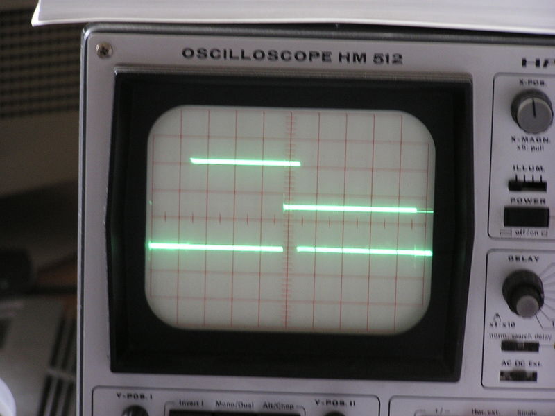
Lower level is keyclock, higher level is keyrow signal - about 3us delayed by increase of capacitance, when sensorpad is touched. It's actually more than expected - IT WORKS!! - all decoding will happen in FPGA.
File history
Legend: (cur) = this is the current file, (del) = delete
this old version, (rev) = revert to this old version.
Click on date to see the file uploaded on that date.
- (del) (cur) 14:35, 31 August 2006 . . Hzulu (Talk) . . 2048x1536 (700932 bytes) (Lower level is keyclock, higher level is keyrow signal - about 3us delayed by increase of capacitance, when sensorpad is touched. It's actually more than expected - IT WORKS!! - all decoding will happen in FPGA.)
- Edit this file using an external applicationSee the setup instructions for more information.
Links
The following pages link to this file:
Metadata
This file contains additional information, probably added from the digital camera or scanner used to create or digitize it. If the file has been modified from its original state, some details may not fully reflect the modified image.
| Image title | OLYMPUS DIGITAL CAMERA |
|---|---|
| Camera manufacturer | OLYMPUS OPTICAL CO.,LTD |
| Camera model | C740UZ |
| Orientation | Normal |
| Horizontal resolution | 72 dpi |
| Vertical resolution | 72 dpi |
| Software used | v754u-84 |
| File change date and time | 08:27, 23 November 2024 |
| Y and C positioning | 2 |
| Exposure time | 1/15 sec (0.066666666666667) |
| F Number | f/3.2 |
| Exposure Program | Creative program (biased toward depth of field) |
| ISO speed rating | 200 |
| Exif version | 2.2 |
| Date and time of data generation | 08:27, 23 November 2024 |
| Date and time of digitizing | 08:27, 23 November 2024 |
| Image compression mode | 2 |
| Exposure bias | 0 |
| Maximum land aperture | 3.4 |
| Metering mode | Pattern |
| Light source | Unknown |
| Flash | 16 |
| Lens focal length | 29.6 mm |
| Color space | sRGB |
| Custom image processing | Normal process |
| Exposure mode | Auto exposure |
| White Balance | Auto white balance |
| Digital zoom ratio | 0 |
| Scene capture type | Standard |
| Contrast | Normal |
| Saturation | Normal |
| Sharpness | Normal |


